The scientific journal "Territoriya "NEFTEGAS"", №12, 2017 - http://tng.elpub.ru/jour/article/view/652
Kachanov, M. O., Tokarev V. G., Kurenkov, A. I., Rybko V. D.
Measuring the level of liquids in process tanks is an important element in the organization of modern efficient technological processes that occur in many industries (storage of petroleum products, chemical processes, transportation of liquefied substances, pharmaceutical production, etc.).
Level meters and level annunciators are produced by many companies, both foreign and domestic.
There are many means of level control and measurement based on different physical methods: capacitive, electrocontact, hydrostatic, float, ultrasonic, radio-wave, isotopic. All these methods used in modern level meters and level annunciators require the installation of their primary transducers inside the controlled tank (except for the isotope method).
Therefore, when you select a level measuring tool, you impact with the following problems:
- it is necessary to take into account such physical and chemical properties of the controlled environment as temperature, abrasive properties, viscosity, electrical conductivity, chemical aggressiveness, etc.;
- it is necessary to take into account the operating conditions in the tank: pressure, vacuum, heating, cooling, filling or emptying method, the presence of internal mechanisms and structures, flammable, explosive and other;
- impossibility, unwillingness or difficulty of changing the design of the tank for some specific cases, for example for high-pressure tanks, tanks containing especially dangerous substances or at especially pure productions.
In addition, various requirements are demanded to devices for measurement the level of filling of tanks and vessels: in some cases, it is necessary only to signal of the achievement of a certain limit value, in others it is necessary to carry out continuous measurement of the level of filling. Therefore, there are two groups of control devices - level gauges and level indicators, which differ functionally and belong to different price categories.
Creation of an annunciator with functions of a level gauge is an important task which allows increasing the convenience and reliability of a non-commercial level control of liquids.
Company LLC "RPE-Technoautomat" has developed a non-invasive ultrasonic liquid level annunciator "Rubin-1M", which is based on excitation and reception probing Lamb waves by ultrasonic sensors in the wall of the controlled reservoir (technological vessel) with its outer side, i.e. elastic ultrasonic wave in which the vibrational displacement of the particles occurs both in the direction of wave propagation and perpendicular to the plane of the wall. The degree of attenuation of the Lamb wave amplitude is determined by the distance traveled by the wave along the tank wall, as well as the absorption of its energy by the environment with which this wall contacts. The latter largely depends on the properties of the environment. The absorption of energy by the liquid differs from its absorption by air environment at times.
This property of the difference in the degrees of attenuation of the Lamb wave at the contact of the wall with different media (gas and liquid) is used in the work of the signaling device "Rubin-1M" which is realized through the excitation of the sounding acoustic wave through different channels including ones duplicating each other as a comprehensive analysis of various parameters of the excited wave, the results of which give in total reliable information both on the boundary positions of the liquid level (the signaling function) and the dynamics of the liquid level change (the level meter function).
The wave process that occurs when ultrasonic vibrations are excited in thin plates, which are the vessel walls, is an inhomogeneous nonlinear configuration of a group of normal waves, which are described by the following equations:
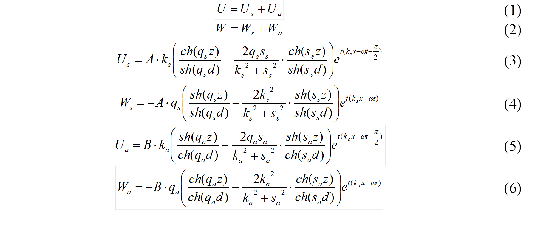
where U, W – components of the total longitudinal and transverse displacements, respectively; Us, Ua – components of the longitudinal displacement, relating to the symmetric and antisymmetric wave, respectively; Ws, Wa – components of the transverse displacement, relating to the symmetric and antisymmetric wave, respectively; A, B – arbitrary constant determined by the initial conditions of excitation; z – transverse position of the point relative to the median plane of the plate; d – plate thickness; x – distance along the plate; ω – circular oscillation frequency; t – time; k, q, s – wave numbers associated relations:

where ks,a – wave numbers related to symmetric and antisymmetric waves, kl, kt, – wave numbers related to longitudinal and transverse waves, respectively. Analysis of the equations shows that most of the energy for the antisymmetric wave is concentrated in transverse vibrations, whereas for symmetric waves, on the contrary, in longitudinal waves. Analytical solution of the task of determining the degree of absorption of different types of lamb waves for specific conditions is quite complex. However, the nature of this dependence can be seen already from the ratio of Rayleigh wave attenuation coefficients, which are most similar to lamb waves of zero modes degenerating in them at d>>λR, where λR is the Rayleigh wavelength. The greatest contribution to the attenuation coefficient of Rayleigh waves is made by transverse waves. The analytical dependence for the attenuation coefficient is expressed by the following formula:

where α – is the attenuation coefficient of the longitudinal Rayleigh wave, β – is the attenuation coefficient of the transverse Rayleigh wave, A – is a value that depends only on the properties of the material, expressed through the Poisson's ratio - ν. For steel, for example, the above expression takes the following form: γ = 0,11α + 0,89β. The latter indicates that the attenuation of these waves is determined generally by the transverse component.
To control the liquid level the device "Rubin-1M" uses a symmetrical Lamb wave of the zero mode as a main one and antisymmetric Lamb wave of zero mode as the most informative for the process. This principle was patented as the measurement technology “TechnoLamb”.
A significant advantage of the device "Rubin-1M", which allows to solve the problems that prevent usage of other level measuring instruments based on a different principle of operation, is its ability to work in difficult industrial conditions, by controlling various aggressive or highly pure substances, excluding the influence of internal structures and processes inside the container. This is ensured by a non-invasive method of monitoring ultrasonic waves propagating in the walls of various tanks, open and closed (wall thickness up to 70 mm).
Also, affordability was achieved thanks to original engineering and design solutions, compactness, ease of installation and ease of use of the device, which implements the functions of self-diagnosis and auto-tuning.
According to the technical requirements and the results of tests at the facilities of JSC “AK Transneft” a new modification of the device “Rubin-1M-NP” was developed on the basis of the “Rubin-1M” level annunciator. This device was designed to control the level of oil in oil pipelines and other apparatuses, such as reception and discharge chambers of treatment shells (scrapers, rubber-cord sealer (RCS)). A distinctive feature of this modification is that it allows not only to fix some limit values of levels, as "Rubin-1M", but also determines the position of the level across the pipe section profile and at the same time captures the moments of passage of cleaning shells and RCS through the pipeline. Fixing of the moment of passage of the cleaning projectile or RCS is carried out at once on two factors: on increase/decrease in level of acoustic noises and on sharp difference of the measured oil level in the pipeline. This device allows to monitor and evaluate the size of gas plugs that arise while filling of a pipeline of oil or its displacement by nitrogen plants during the passage of treatment shells or RCS through the pipeline, as well as determine the residual level of oil in the pipeline after its release multichannel measurement of ultrasonic signals in several areas along the contour of the cross section of the pipeline were " implemented in the device "Rubin-1M-NP”. This technical solution received a patent of the Russian Federation for the invention № 2608343 of July 31, 2015 "Method for controlling the level of liquid in tanks on the characteristics of the lamb waves and the device for its implementation".
The control scheme implemented in the device" Rubin-1M-NP " allows, to automate the process of configuring the device and calibrate it immediately when it is installed on the object due to analyzing the ratios of signal levels in different areas When the device is started, the operator sets only the parameters of the object: the diameter of the pipeline and the thickness of its wall, the type of insulation and the type of liquid in the pipe. Other measuring parameters (the gain factors of the measuring channels, the coefficients of attenuation of signals at the measuring stations and the initial setting of the signal levels at the "gas" and "liquid") the device identifies itself.
The measurement process begins with the fact that at first, the ratio of signal levels in different parts of the circumference of the pipeline profile relative to certain level settings for "gas" and "liquid", calculated during calibration, is determined roughly at what section is the level. Then, the value of the arc length of the circle of the area being in contact with the liquid is calculated. This uses the logarithmic approximation for the function of the attenuation of the ultrasonic lamb wave signal.

where: Lж – is the length of the arc in contact with the liquid for the corresponding measuring channel; K – reduced signal attenuation coefficient (determined during calibration, automatically); А – the current amplitude of the signal; UГ – amplitude setting for gas. The current position of the liquid level in the pipeline is calculated according to the found length of the arc being in contact with the liquid, in accordance with the geometry of its location on the cross-section of the pipeline. For example, Fig.1 shows schematic cross-section of the pipeline, the location of sensors on the wall of the pipeline and the scheme for calculating the liquid level.
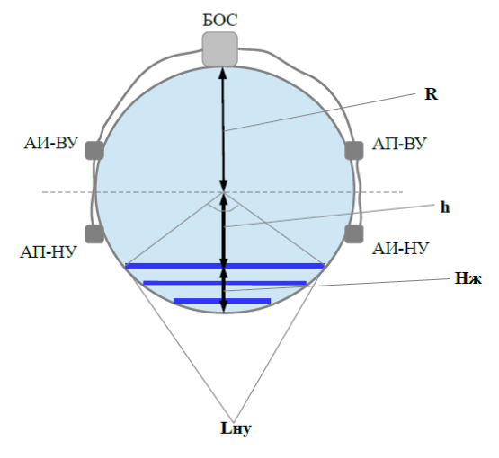
Fig.1 Scheme of location of sensors and calculation of liquid level in the pipeline
БОС-signal processing unit, AИ-ВУ-acoustic top-level emitter, АП-ВУ-acoustic top-level receiver, AП-НУ-acoustic lower-level emitter, AИ-НУ-acoustic lower-level receiver, R - the inner radius of the pipeline, h – the distance from the middle of the pipeline to the liquid level, Hж – liquid level, Lну – the arc of the liquid on the lower measurement channel.
The device monitors the acoustic noises that occur in the wall of the pipeline section where the sensors of the device are installed simultaneously with determining the position of the liquid level in the pipeline or other closed apparatus of circular cross-section,. This control allows to reliably track not only the current filling level of the pipeline fluid, but the time when the scraper is passing and also to detect the "whooshing" of valves of the receiving and exhaust chambers in the case of violations of their integrity and the appearance of possible leakages. Thus, the fixation of the increase in the level of acoustic noises and the occurrence of failures of the measured level can significantly improve the reliability of such a combined control.
The uniqueness of the technology based on the control of lamb waves made it possible to provide multifunctionality in one device and significantly improve its efficiency when monitoring the integrity of the receiving and starting chambers in comparison with existing devices, such as ДГК-1-3д.
Currently, the device has successfully passed a number of technological tests in industrial conditions at the facilities of JSC “AK Transneft”. A mobile portable version of the instrument which can be used autonomously in the field, both for control at the sections of the oil trunk pipeline and other technological devices has been prepared,. Works on certification of the device and patenting in the EU countries are conducted. Photo of the device "Rubin-1M-NP" in mobile execution and the results of last tests on the real objects are presented in the figures below.
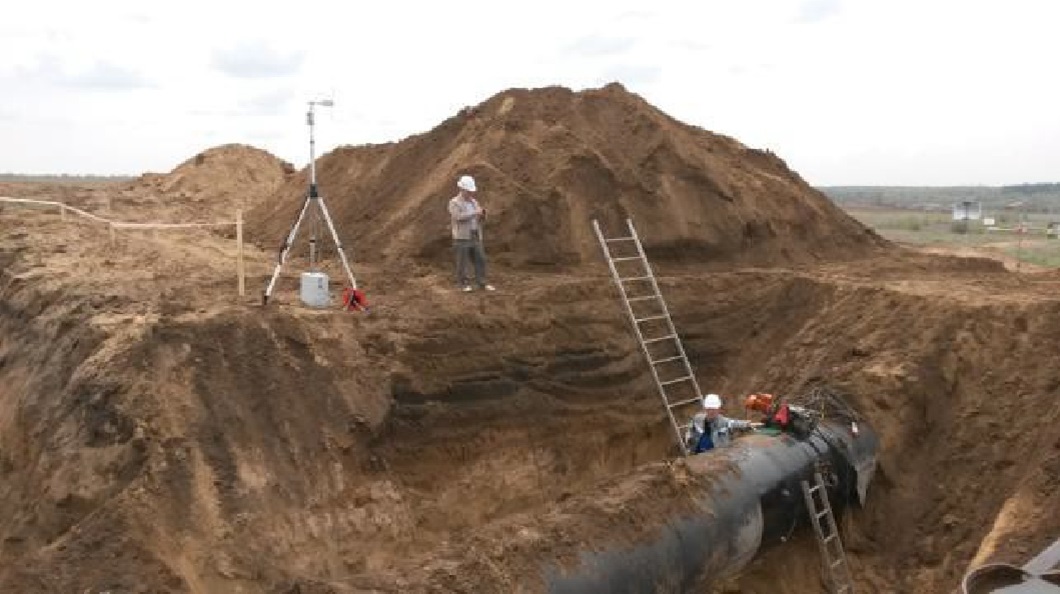
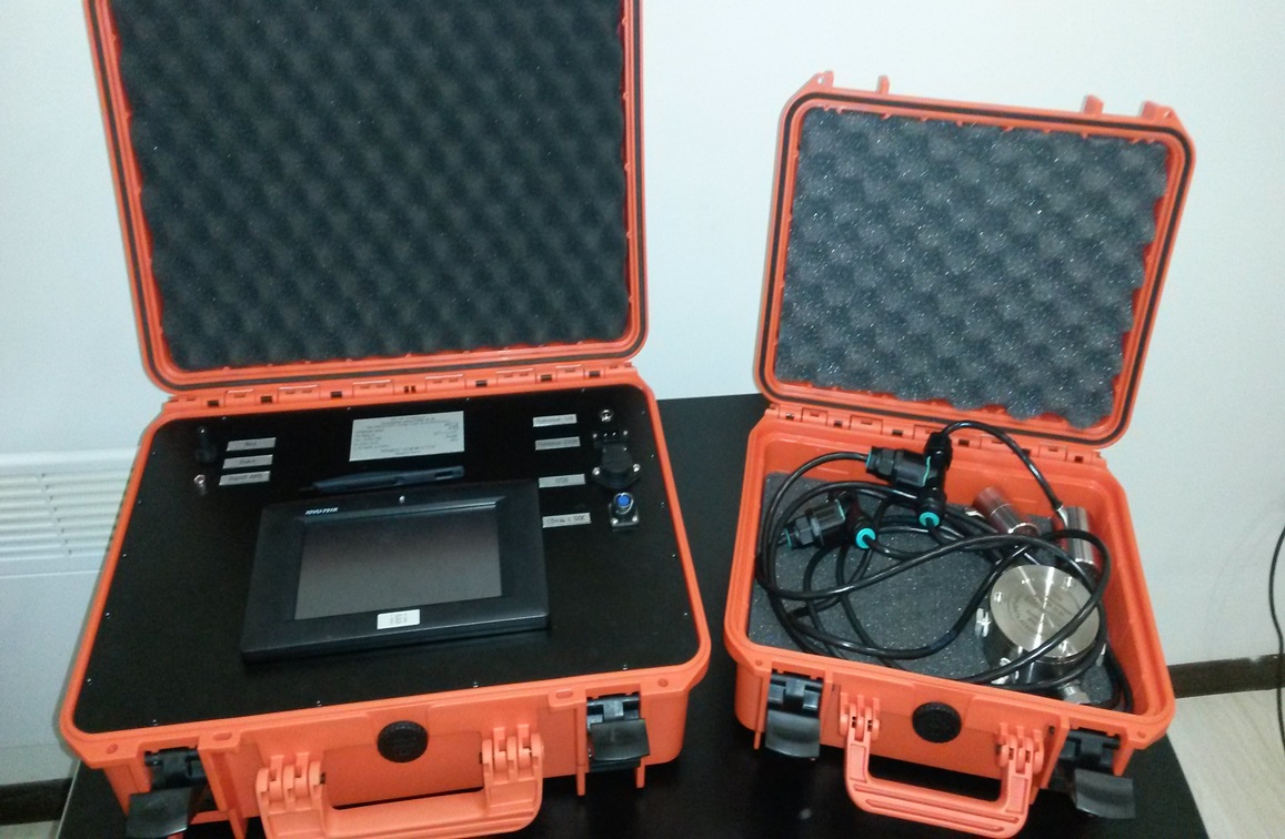
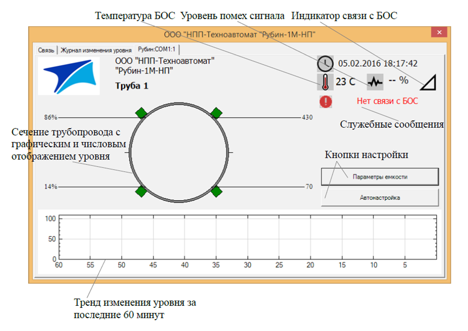
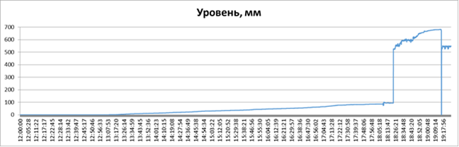
Fig.2. Graph of oil level change at the control point of the pipeline. X axis - time in the format HH:MM:SS, Y axis - level in mm
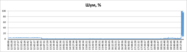
Fig.3. Graph of noise level in the control point of the pipeline change trend.
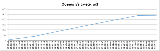
Fig.4. Graph of the calculated volume of the gas-air mixture passed through the section of the pipe (at the nominal speed of the piston, taken equal to 1 km/h). X-axis – time in the format HH:MM:SS, Y – axis, the volume of the gas-air mixture in m3
The approximate volume of air-gas mixture passed through the section of controlled part of the pipe may be calculated by the average velocity of the RCS moving through the pipe according to the following formula:

where: V – is the current volume of gas passed through a section of pipe; V0 - is the volume of gas passed through a section of pipe in the previous time; U – the average velocity of the piston or RCS; t – current time, t0 is the previous moment of time; R – is the internal radius of the tube; L – is the current level of oil in the tube; Knowing the pressure at this portion of the pipe it is possible to cause the gas volume to normal conditions.
Summary:
1. Application of noninvasive ultrasonic technology of control of propagation of Lamb waves in the walls of tanks allowed providing combined measurements of several technological parameters in one device, namely:
- measure the oil level in the pipeline to an accuracy of 5% of its diameter with automatic calibration;
- to determine the passage of a cleaning projectile or RCS with high reliability;
- to fix passing of gas "bubbles" in the pipeline and to make an assessment of their sizes;
- to diagnose leaks by the noise spectrum of the signal.
2. Application of the control scheme implemented in the device" Rubin-1M-NP " can significantly improve the quality and reliability of monitoring the process of oil transportation through pipelines.
3. It should be noted the economic efficiency of the device, because in fact one device implements several functions, and is very simple and easy in operation.
4. The unique capabilities of this method of control allow predicting its widespread usage in various industries in the Russian Federation and abroad.
Authors:
Oleg M. Kachanov - General Director of LLC “RPE-Technoautomat”
Viacheslav G. Tokarev - Chief Engineer of LLC “RPE-Technoautomat”
Anton I. Kurenkov – leading engineer of LLC “RPE-Technoautomat”
Denis V. Rybko - leading engineer of ACS TP JSC “Transneft-Privolga”