Scientific and technical journal "Exposition Oil Gas», №5 (23), 2012.
Kachanov O.M., Tokarev V.G., Romanov A.V., Kurenkov A.I.
In modern technology of liquid level control ultrasonic methods firmly took thier place. These methods use dependance of parameters of ultrasonic vibrations from the environment in which they are distributed. Main widely used at the present time ultrasonic methods for liquid level measurement are based on measuring the amplitude, or propagation time of the direct and (or) reflected from the liquid surface ultrasonic waves and also ones propagating in special probes that come into contact with the liquid. This is so-called methods of echolocation.
The accuracy of these methods depends on the properties and parameters of the medium (air or gas above the liquid surface, the liquid itself, the material of the tank wall and the probe) and their stability during the measurement. To ensure the accuracy of measurements of these methods it is necessary or to specify in advance a limited range of variation of these parameters or to introduce an additional control, allowing to make operational adjustments of the measurement results. The first technique is to be achievable usually rigid stabilization of processing modes that can be practically very difficult. This narrows the scope of use of technology of such admission. The second one complicates the instrumentation. The complexity of this will be determined by the "complexity" of the environment and its behavior in the process taking place in the tank.
These methods, anyway, for reducing the impact of environmental parameters require tapping the primary measuring converters directly to the tank, process vessel. This inevitably leads to a constructive complication of the instrumentation. In addition, the majority of technological processes in the industrial sector are not "clean". The demand for purity of measurement units are generally much higher than to the actual technological devices. This imposes additional requirements to comply with routine maintenance, their periodicity.
In recent years, other method of ultrasonic testing began to find application which uses the properties of so-called Lamb waves propagated in thin plates, which are the walls of the tank. It is known that the degree of absorption of the energy of oscillations of these waves depends essentially from the contact surface of the plate with the environment, its properties and mostly its density and viscosity. In gaseous and liquid mediums these parameters are vary in order, so the degree of absorption signals distributed on the vessel wall along a line which is only in contact with the gaseous environment may be different in times from that on the inner surface in contact with liquid, at equal distances. Thus, measuring the degree of damping of oscillations of the ultrasonic waves on a fixed portion of the tank wall between their transmitter and receiver located on its outer surface, one can determine the position of the line between the liquid and gaseous phases, relative to the line of propagation of the waves.
The advantages of this method are obvious. This method does not require tapping primary converters into the reservoir since the excitation and monitoring ultrasonic Lamb waves produced at its outer surface, which greatly simplifies the design of the transducers and their assembly on site. The composition and pressure of the gaseous medium in the container do not have any practical effect on the measurement results in this method and it is insensitive to fluid density.
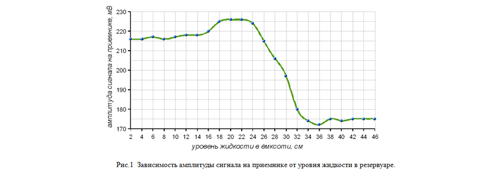
This method is implemented in level detector "Rubin-1M". This device is serially produced by "RPE-Tehnoavtomat" (Engels) since 2006. The device has two pairs of ultrasonic transducers to control the two limit positions of liquid level in tanks, which are installed on the outer surface of the tank in parallel to the liquid level in the controlled marks. It provides a discrete indication of the current situation regarding the level of the liquid reletive to lines of installed converters (above - below), and can measure the liquid level position relative to established lines of converters. Ultrasonic Range of Lamb waves provides the work of the method in the metal wall of the tank till 70 mm. The transition zone of level position, causing the change in the display is determined by geometrical dimensions of primary devices, Lamb wave characteristics, on which the device is set up , and other device settings. The width of this zone can be in the range from ± 5 mm till ± 50 mm. Fig. 1 shows the dependence of the signal unit from the liquid level in the tank. The characteristic signal emissions at the edges of the transition zone are connected with the so-called edge effect. The size of "spread" of the transition zone is comparable with the wavelength of the Lamb wave, and does not exceed it.
As it was shown by the test, the key destabilizing factors affecting the measurement of the external temperature are the ambient temperature and the tank walls, which define the operating temperature of the source and the receiver, and status of the internal surface of the tank, above all, its degree of contamination of the different sediments with a viscosity greater than the viscosity the main liquid.
Temperature affects mainly on the transmission characteristics of the transducer elements themselves and other auxiliary materials used in the construction of the transmitter and receiver, as well as the lubrication of the contact surface of the reservoir. Theoretically, the temperature throughout the industrial range (-50 ° C ÷ + 50 ° C) should not significantly affect the parameters of attenuation of Lamb waves in the metal, however, in practice, is still there. Perhaps the explanation for this phenomenon is due to additional stresses caused by thermal deformation of the tank structure and design elements of sensors themselves. The second component of the influence can be reduced by improving and testing the process of manufacturing the sensor, however, it does not eliminate this completely.
Introduction of direct temperature compensation in this method is technically difficult. The difficulty of this is that the dependence of the transmission of the temperature for the system: transmitter-receiver-tank wall, generally speaking, the individual. This dependence is not described by a strict repeatable curve. It is more like a complex hysteresis. However, for most applications, with the existing technology scatter of characteristics of converters, the dependence of the transmission of the temperature will not go beyond certain limits.
To solve the problem of increasing the stability and accuracy of measurement results in the instrument "Rubin-1M" is not used the direct method of measuring the signal amplitudes but the ratio of the energy characteristics of some of them. This method and its realization in the device are protected by a patent [1]. In the device a transmitter and receiver use identical pair of piezoelectric transducers X-cut, arranged perpendicular to the surface of the plates. Excitation is performed by leading edge of periodic pulses (single exposure impact), the duration of which exceeds the propagation of surface waves of the Rayleigh the distance between transmitter and receiver. Referring known [2], this method of excitation leads to the simultaneous rise in the plates mostly symmetric and antisymmetric Lamb waves of zero order. It is also known that the Lamb wave is a heterogeneous group of non-linear configuration normal waves, which are described by the following equations:

where - the total components of longitudinal and transverse displacement, respectively; - Longitudinal displacement components related to the symmetric and anti-symmetric wave, respectively; - Transverse displacement components related to the symmetric and anti-symmetric wave, respectively; - Arbitrary constants determined by the initial excitation conditions; - Cross-point position with respect to the mid-plane of the plate; - The thickness of the plate; - Distance along the plate; - Circular frequency of oscillations; - The time; , - The wave numbers associated relations:

where - the wave numbers relating to the symmetric and antisymmetric waves - wave numbers relating to the longitudinal and transverse waves, respectively. An analysis of the equations shows that most of the energy for the anti-symmetric wave concentrated in the transverse vibrations, whereas for symmetric, on the contrary - in the longitudinal. Analytic solution to the problem of determining the degree of absorption of different types of Lamb waves for specific conditions rather complex. However, this dependence is already visible in the ratios of the coefficients of attenuation of Rayleigh waves, which are most similar to the zero modes of Lamb waves degenerating into them when, where - the length of the Rayleigh wave. It was shown [2] that the greatest contribution to the attenuation factor of the Rayleigh waves are making transverse waves. Analytical dependence for the attenuation coefficient expressed by the following formula:
![]()
where - coefficient of attenuation of the Rayleigh wave longitudinal - transverse damping coefficient of Rayleigh waves, - a certain quantity depending only on the properties of the material, expressed in terms of Poisson's ratio. For steel, for example, the above expression becomes:. The latter indicates that the attenuation of these waves is determined to a greater extent transverse component
This fact has a different effect on the degree of absorption of the fluid contact layer symmetric and antisymmetric Lamb waves, similar to Rayleigh that reliably confirmed by the experiments. Separation of signals relating to the symmetric and antisymmetric wave signature in the common signal is gated in the unit of time of two portions, as the propagation velocity of these waves are different. The reference signal is received relating to a symmetric Lamb wave, since the degree of energy absorption symmetric Lamb wave is approximately 2 times less than the zero-order anti-symmetric to the one in contact with the plate surface and the liquid maintains the stability of the characteristics over a wide temperature range. Furthermore, the use of this signal as a reference improves noise immunity of the device, which is easily separated at the beginning of "clean" portion of the same signature, devoid of reflected signals as a symmetric Lamb wave velocity zero mode is the highest in comparison with other components. Thus, the use ratio of the two signals eliminates the influence of the temperature trend in the final measurement result, leaving in it only the degree of absorption between the two types of waves.
During the commercial operation of the device "Rubin-1M" we also faced another challenge. This is so-called "noisy" objects. These primarily include gas separator vessel, in which gas is supplied under high pressure through the shut-off control valves. In the process, there may be such technological modes, when the armature begins to "whistle", causing acoustic noise in the walls of vessels passed through pipelines, associated with it.
Running tests of level detectors "Rubin-1M" on the real existing facilities have shown that the measuring instrument is subject to the signature of a noise fluctuation and distortion under the influence of acoustic noise associated with the workflow in the apparatus. The most noticeable effect is that the characteristics of the selected time zone signals are beginning to go beyond the custom settings and the device can produce a false definition of the situation of the liquid. This was observed in some of the gas separator, a source of acoustic noise that is input Valves operating at high differential pressures with the emergence of vibration and gas "whistle". During the tests integral characteristics of these noises transmitted to the working surfaces of the separator tank (average values of speed, acceleration and amplitude of vibration) were revealed . The frequency characteristics of the running noises were clearly non-stationary, so the use of band-pass filters in this case was ineffective.
To suppress (reduce the impact) of such interference in the signal processing a special filter was introduced into the software, as additional configurable option. This signal processing takes into account the following factors: – - The influence of noises on the different parts of the signature of the signal distribution in time is not the same, ie. the probability of simultaneous equal (similar) distortions of two sites is significantly less than the selected one, during normal operation. This factor serves as an additional criterion for the selection of less distorted signatures signals; – Trend velocity of parameters of signature signals during normal operation, is determined by the drain / filling of liquid into the tank. This fact is used as a restriction on the actual change in the value of selected parameters between measurement cycles. –Total allowable noise level is determined by the device in the initial zone of the signature of each measurement cycle, before the advent of useful signals, serving as a kind of indicator of normal operation of the device at the same time blocking the criterion of false positives. Thus, for implementation of the method of processing measurement signature software filter includes the following input parameters are configurable: – N - the number of signatures in the measuring cycle; – T - between the measuring cycles; – Z0, D0 - delay and width of the initial measurement window in the signature, respectively (to determine the level of interference) – Z1, D1 - a delay and width of the first measuring window in the signature, respectively (for the determination of the reference signal); – Z2, D2 - delay and width of the second measuring window in the signature, respectively (for determining the level of the desired signal); – K - initial ratio between the received parameters signature measurement windows (ratio between A1 / A2 or I1 / I2, depending on the job A / I); – А/I - specified parameter measurement window, the amplitude or integrated; – А1/I1 - the initial value of the selected parameter of the first, main, measurement window; – So - the threshold noise level; – Sk - permissible deviation from the current value of K to be used for the selection of measuring the signatures in the current sample; – Sa/i - - tolerance of a given parameter of the main measuring window of the previous value, calculated as the average of the number of selected signatures in the current sample.
The input filter parameters are set by the operator based on the actual conditions of the controlled object on the basis of the analysis of the preliminary test, is not treated signatures. The processing procedure of signatures includes the following steps. First, several cycles of measurement are performed , from which the noise level exceeds the threshold value are excluded. The selected window N measurements with the highest possible rate to a primary converter, among which are selected those with the current value are stored

Then the average value of the parameter A / I on selected signatures is determined . If the resulting value is satisfied the condition

then this value is acceped as a current value and the measured value of a subsequent cycle is regarded as the primary. If,

then, the current value becomes

If,

then, the current value becomes

In all cases, the average value of K on selected signatures is calculated and this value is taken as the initial value for the next measurement cycle. For the final configuration it is important to have current information on the number of selected signatures. It is, of course, should not be zero, and do not to approach the predetermined value N. The latter is possible only when there is no interference. Optimization of the filter should be achieved by selection of the values of Sk Sa / i. The first, as shown by operation, the correct choice of the measuring window of a few tenths of K (the ratio depends little on the change of position with respect to the liquid level sensor), and should be kept to the minimum necessary, providing a non-zero number of samples (preferably, up to N / 3), the second should not be reduced to a minimum, in cases where the rate of discharge / loading is high and requires a quick response to activation of the device. N - imposes a restriction on the speed of processing and memory capabilities signatures primary converter device. Very important is the correct definition and initial job K. correctness criterion may just serve the current value of the amount shown in filters signatures, sustainable swing around a certain value. It should not be less than three, if the filter is applied discarding extreme values before determining the mean value. Not quite right assignment of initial values A1 or I1 is not critical. The job will lead to some delay in the correct reading device at the initial stage (entry mode). It is important that during this delay, the position of the liquid level has not changed. Time to correct mode will be several periods of measuring cycles, depending on the size mismatch and Sa / i. T - is limited on the one hand, the duration of the duty cycle of the secondary drive, on the other, the rate of reaction of the device. It will be appreciated that this parameter correlated with Sa / i, the value of the latter should be calculated on the basis of T and the maximum rate of change measurement parameters determining the rate of discharge / loading of liquid in the tank.
The results:
1.Practical implementation of promising method for liquid level control for closed tanks is presented.
Conclusions:
1. Presented procedure of treatment of the routine signature signals, providing the calculation of the ratio of the energy characteristics of zero modes of the symmetric and anti-symmetric Lamb waves and the introduction of special software filter improves the accuracy and stability of measurements in real conditions.
Used Books:
1. Tokarev V.G., Kachanov O.M., Kurenkov A.I., Romanov A.V. and Romanov M.V. Patent G01F 2/296 (2006.01) “Method of ultrasonic liquid level in tanks and apparatus for ultrasonic liquid level in the tanks”. 2. Viktorov I.A. The physical basis for the use of ultrasonic Rayleigh and Lamb waves in the art. M .: Science, 1966